|
HOME
|
Back to the main home page and front menu |
|
I have not had much time to get many items in the forsale area below. Please keep checking back as I will start adding more items soon. Items
For Sale |
Switch Material Electrical Code Mica Insulation CP or WATTS Marks Socket Bead/Rib/UNO Catalogs & Ads Patents Pull Chains / Finials Bulb & Socket Bases View images of the most well known bulb and socket bases |
|
Socket
& Electrical Manufacturer's Items And Their History
|
| GECO
Sockets This section will allow you to date and learn how to tell one GECO socket from the other. Hubbell This is where this site started from. Since this page was done, there has been much more Hubbell history and information found which will make for a complete redesign of this page and section in the soon future. Hubbell Patents This section has some early patent research on Hubbell. It is mostly complete with only a few missing patents which will be added in when this section is re done into the new format Wheeler Reflector Co. A history of The Wheeler Reflector Company and tips on how to tell if mirror has been replaced on a shade Other Manufacturers This section is a lot of incomplete work and will be updated shortly. For now it serves to give you some extended information on some companies, but will be a much better tool when it is complete NEC This section is everything you ever wanted to know about the National Electrical Code (NEC) but had no one to ask. Downloads of old NEC's, meetings and much extended information is provided. Cord Balls & Adjusters My cord pendant adjuster project, as well as a good history about them. |
| GECO
Sockets More companies will be added to this list in the near future. We will also be adding a new list of post 1900 sockets and items. Bergmann & Co. Brush Electric Co. Bryant Electric Co. Crown Elect MFG Co. EE&S Holmes & Gale (HG) Perkins Thomson-Houston Westinghouse |
|
Tutorial
And Early Lighting History
|
|
To
read the entire tutorial, you can just click on the first link and
then continue to the next section at the bottom of each page. Or,
you can select links below of interest to you. |
  |
THIS PAGE WAS
CONTINUED FROM HERE The
Edison No. 1 socket is basically any socket configuration that uses
baseless bulbs and before the invention of the screw base.
I
have two sources that document the Edison No. 1-C socket and so
far examples of two possible different configurations of it which
are shown below. Please note that the second example has not yet
been documented as actually existing in real life. The first and
top socket picture below came from an ebay auction from many years
ago. The second socket picture (shown below on the bottom) came
from photos taken by Tim Tromp of the Dr. Hugh Hicks collection
back in 1999. (Tim Tromp is the owner of Kilokat's
Antique Light Bulb Site 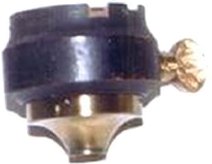 After
the Menlo Park demonstration of December 31st 1879, Edison started
getting ready for the next demonstration. The first improvements to
be addressed was how the bulb attached to the socket; and how the
socket switched off and on. Keeping in mind that the first (No 1)
sockets could only be used in an upright position, Edison knew that
this was the first improvement that he needed to make in the socket. After
the Menlo Park demonstration of December 31st 1879, Edison started
getting ready for the next demonstration. The first improvements to
be addressed was how the bulb attached to the socket; and how the
socket switched off and on. Keeping in mind that the first (No 1)
sockets could only be used in an upright position, Edison knew that
this was the first improvement that he needed to make in the socket.
In his new patent application he first gives the application number for the old socket filed by him, he then goes on to say: "In such the lamp is held to the socket by friction between the neck of the lamp and the socket. It is desirable, however ...to hang the lamp from the socket or to support the lamp horizontally." This No. 2 "Screw Shell" socket, was applied for patent on March 26th 1881 and approved on December 27 1881 and was assigned patent No. 251,554. Even though the patent was applied for late, it can be documented as being used in late 1880. This is what also makes it important to note this design patent from 1880 which was for a bulb that could only be used in this socket. It was applied for on November 30th 1880 and assigned design patent no. D12,631. 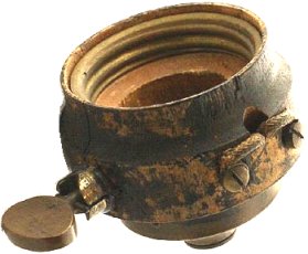
DATING THE NO. 2 EDISON SOCKET I must admit that this has been one of the hardest sockets to put a date on, as it was not well documented in history. This is likely due to the fact that it only lived a very short time. The late patent dates do not help in this matter either since they were filed after it was already in use for some time. We already dated it to Nov. 30th 1880 by proving that a bulb existed at that time (but in the strict purest sense, this is not the socket). There is not doubt to the No. 2 being an 1880 socket, but how close can we date it by digging for different kinds of documentation? Francis Jehl 'reminisced' about this socket in when telling the story: "When preparations for the second exhibition got underway, Edison took up the subject of socket and lamp base again. He knew these must be constructed so that the lamp could be held securely in any position, and at the same time furnish a good electrical connection." "One night in the early part of 1880, while the master was talking on the subject to some of his assistants, he noticed a kerosene oilcan standing near. Taking it up and unscrewing its cover, he studied the combination for a while and then exclaimed, 'This most certainly can make a bang-up socket for the lamp, as well as a base!' Thus the Edison screw socket and lamp base of 1880 were born." (Menlo Park Reminiscences vol. 2 pages 740-741) From researching through the Menlo Park notebooks, technical scrapbooks, documents, etc., I found that the bulb to socket attachment method was the attention on many drawings during early 1880 to late 1891. I should also mention that I could not find any reference to it being called a "Bang-up" socket, but several references to it being the "Screw Shell". I looked for this because I had found a collector referring to this socket as the "Bang-up" socket. So far, I count this "title" as an undocumented reminisced name for the socket and will simply call it the No. 2 Edison Screw Shell socket on this site (unless future documentation surfaces). 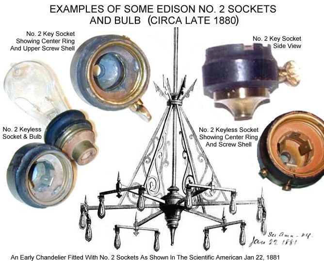 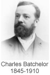 EARLY
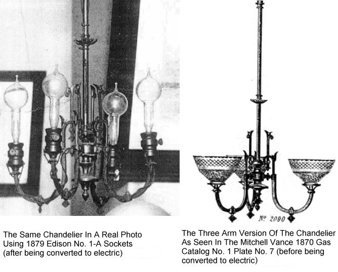
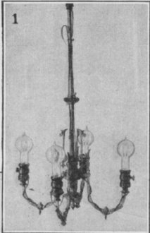
FIXTURES Documented Using No. 2 Sockets EARLY
FIXTURES Documented Using No. 2 SocketsThe engraving of the chandelier shown above was taken from a series of Menlo Park scrap books archived by the Edison Lamp Company. The scrapbooks are documented as the Charles Batchelor Scrapbook Collection Batchelor was one of Edison's closest laboratory assistants and business partners. This chandelier engraving was found in the 1878-1881 scrapbook volume, originating from a Scientific American magazine article that was hand dated Jan. 22 1881. Charles Batchelor (shown in the picture on the right) also signed and witnessed most of the drawings in the 1880 Menlo Park technical notebook no. 60 (talked about on this web page and found in the sections directly below). The Scientific American Vol. XLIV. No. 4 of January 22, 1881 as well as the article as archived in the Charles Batchelor scrapbook has been linked here along with some close up photos taken by Adam Allerhand.  In
the Menlo Park technical notebooks almost two entire volumes* are
taken up with drawings of a project which included chandeliers, hall
lights and wall brackets, as well as the parts needed to be manufactured
and used on them (such
as holders, sockets, etc.) In
the Menlo Park technical notebooks almost two entire volumes* are
taken up with drawings of a project which included chandeliers, hall
lights and wall brackets, as well as the parts needed to be manufactured
and used on them (such
as holders, sockets, etc.) As seen in these notebooks, Edison conceived and designed most of the technicals such as motors and regulators, E.H Johnson (under Edison's direction) the final sockets and John Ott (Edison's principal model and instrument maker) was the person that manufactured and assembled most of the chandelier parts (including the sockets). *(these two volumes are 1880-1881-Menlo-Notebook-No-153-Sept-to-Feb & 1880-Menlo-Notebook-No-60-Oct-to-Nov)  The
chandelier sections appear to have been completed
mid November of 1880. It is also noteworthy that this chandelier
project (as being seen in the notebooks), appears to have been a work
in progress for the entire system (which would not be complete until
every part in the system that was needed to make it work, were also
completed). These two notebooks document the making and design of
a regulated motor, sockets, switches, proper wire to be used from
many samples requested, etc.. They also document designs for the making
and wiring of what appears to be a matched set consisting of chandeliers,
wall brackets and hall lights that have the fixture wire running inside
the tubing (and not wrapped around the outside of the fixtures as
in the old converted gas fixtures of which there were many of in those
days). The
chandelier sections appear to have been completed
mid November of 1880. It is also noteworthy that this chandelier
project (as being seen in the notebooks), appears to have been a work
in progress for the entire system (which would not be complete until
every part in the system that was needed to make it work, were also
completed). These two notebooks document the making and design of
a regulated motor, sockets, switches, proper wire to be used from
many samples requested, etc.. They also document designs for the making
and wiring of what appears to be a matched set consisting of chandeliers,
wall brackets and hall lights that have the fixture wire running inside
the tubing (and not wrapped around the outside of the fixtures as
in the old converted gas fixtures of which there were many of in those
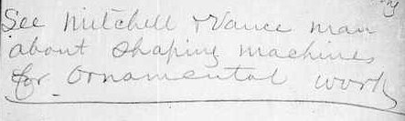
days).It is noteworthy that several illustrations shown for the chandelier wiring, matches the chandelier shown above in the Scientific American article. An example of this is shown in the illustration shown below. This illustration is only one out of many that show wiring for a chandelier from arm to arm, socket to socket, chandelier to switch, lighting to dynamo, etc. 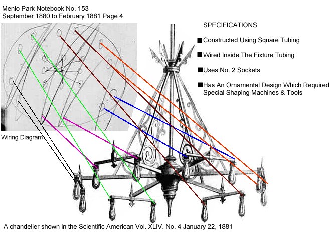 Since on the topic, it is also noteworthy that the design for the chandelier matches the Hall Light design shown in the Menlo Park Notebook illustration shown below. It uses the same square tubing coming down at the same angle as shown in the illustration. While this is not proof positive that this chandelier shown in the Scientific American is the same being constructed in this Edison lighting ensemble, it does provide strong circumstantial evidence together with dating. 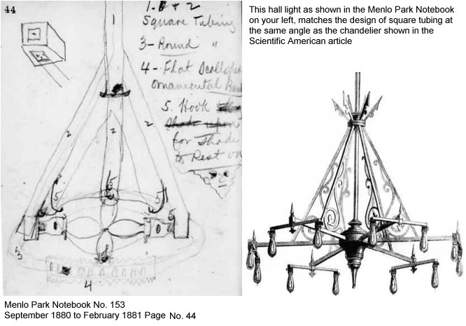 As shown below, the Mitchell Vance chandelier company was consulted on shaping machines needed for the ornamental work on the new chandeliers, which explains the obvious Mitchell Vance shape and design at the top and how the supporting bars meet together on the chandelier arms. Also note that shaping machines would not have been needed for gas conversions. These were newly designed chandeliers being made from scratch.
EARLY GAS TO ELECTRIC CONVERSIONS  Around
this time in history, there are also some documented gas fixtures
that had been converted to electric. One of these has been talked
about in many publications as hanging in the private residence of
Francis R. Upton. Around
this time in history, there are also some documented gas fixtures
that had been converted to electric. One of these has been talked
about in many publications as hanging in the private residence of
Francis R. Upton."The chandelier that Upton had in his private residence near the railway station at Menlo Park was fitted with these new type sockets having snap keys. Often the distinguished visitors who came to the laboratory inspected the lights and sockets at Upton's house. The lamps in the Upton chandelier were all placed in an inverted position in contrast with those used in the first sockets." (Menlo Park Reminiscences vol. 2 page 742) Francis Arthur Jones was the author of a book called Thomas Alva Edison published in 1908 In the Jones book we get a bit more detail:
The Electrical Engineer published an article about this same chandelier entitled "The First Incandescent Chandelier" on August 12th, 1891 Vol.12 Page No. 155 (broken link) The Francis Upton Chandelier Dilemma I should mention that there is some confusion in my mind about what is being called "The Upton Chandelier" as well as the reference to it being the "First" chandelier. Also, what this was actually meant to mean, as seen in the original 1891 Electrical Engineer article (broken link). We need to first pay close attention to the article itself, since the statements shown above (as well as in other books and publications) are most obviously plagiarized and not "direct quotes" from it. Since some statements found in publications have been made without quoting the source, statements have been made that have been interpreted improperly or hyped in the wrong direction. This now causes there to exist multiple sources seeming to tell the same basic story. Remember that each time it is copied by a new source, it is slightly changed by using add-lib in different directions - which have been made up from their own understanding of their particular individual plagiarized source. If this questionable story originally found in this Electrical Engineer article, is reused over and over again (from what ever version down the tree) without being directly quoted, soon it will be even worse then it is now. Adam Allerhand put together an excellent color coded comparison chart (broken link) that helps to quickly point out the obvious plagiarism. 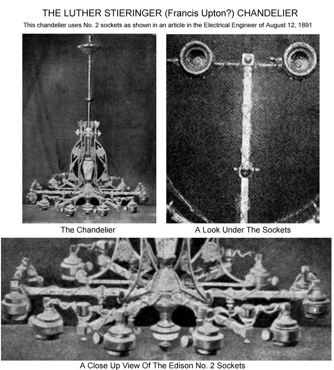 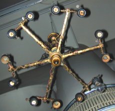 It
would be important to note that the other chandelier shown in this
section (from the Scientific
American), is a 'true first' (being documented)
in the sense that the fixture wires run through the inside of the
tubing and was designed from the start as an "Electric"
chandelier. It was not an existing gas chandelier that had been
converted to electric. Please do not misunderstand me, I am not
saying the the Scientific
American was "without a doubt" the first;
But what I am saying, is that this one shown in the Electrical Engineer
article (the Stieringer/Upton), truly does not directly qualify
for this status. It
would be important to note that the other chandelier shown in this
section (from the Scientific
American), is a 'true first' (being documented)
in the sense that the fixture wires run through the inside of the
tubing and was designed from the start as an "Electric"
chandelier. It was not an existing gas chandelier that had been
converted to electric. Please do not misunderstand me, I am not
saying the the Scientific
American was "without a doubt" the first;
But what I am saying, is that this one shown in the Electrical Engineer
article (the Stieringer/Upton), truly does not directly qualify
for this status.The photo shown on your right, was taken by Tim Tromp (the owner of Kilokat's Antique Light Bulb Site) at the Henry Ford Museum. You can view a few more high resolution pictures with close up pictures of the sockets and cross arms in this pdf (broken link). WHY IT CAN'T BE THE "FIRST"  Let
me explain: First, you need to take into consideration the original
source of the information, which was given to the Electrical Engineer
by the new owner of it (Luther Stieringer) who was a big "collector"
of Edison relics. Many times with collectors, stories are invented,
stretched or simply misrepresented to enhance what they own (or
to put it more simply and truthfully - what they don't own). Second,
the fact that there were other gas chandeliers in history that were
converted to electric is documented fact. There were many such chandeliers
and gas fixtures that had been wired for electric. In the December
31st 1879 Edison demonstration Edison had taken two of his gas chandeliers
and wired them with No. 1-A sockets pointing straight up. Upton
also speaks of a chandelier in a personal letter to his father dated
Dec. 28th 1879 - "I had a number of gentlemen in my parlor
among them the correspondent of the London times. He made a note
of my chandelier" (this was not the one with these No.
2 sockets). There is also another in Menlo Park technical notes
from Upton while documenting filaments in his January 2, 1880 entry
"217. Burnt 4 days. Chandelier over Griff.s desk. Broke
1/4 inch above regular place, probably bad vacuum. Edison brought
this to me." Let
me explain: First, you need to take into consideration the original
source of the information, which was given to the Electrical Engineer
by the new owner of it (Luther Stieringer) who was a big "collector"
of Edison relics. Many times with collectors, stories are invented,
stretched or simply misrepresented to enhance what they own (or
to put it more simply and truthfully - what they don't own). Second,
the fact that there were other gas chandeliers in history that were
converted to electric is documented fact. There were many such chandeliers
and gas fixtures that had been wired for electric. In the December
31st 1879 Edison demonstration Edison had taken two of his gas chandeliers
and wired them with No. 1-A sockets pointing straight up. Upton
also speaks of a chandelier in a personal letter to his father dated
Dec. 28th 1879 - "I had a number of gentlemen in my parlor
among them the correspondent of the London times. He made a note
of my chandelier" (this was not the one with these No.
2 sockets). There is also another in Menlo Park technical notes
from Upton while documenting filaments in his January 2, 1880 entry
"217. Burnt 4 days. Chandelier over Griff.s desk. Broke
1/4 inch above regular place, probably bad vacuum. Edison brought
this to me."In the Electrical Engineer article it says "The chandelier of which an illustration is shown on this page is one of the most interesting relics of the early days of incandescent lighting. It is, in a word, the first chandelier ever used for the specific purpose of carrying incandescent lamps." Not true, but it was possibly the first converted gas chandelier to have the sockets turned in the downward position.
 One could also assume that the Stieringer/Upton chandelier was the one that Upton owned and spoke of in his letter of December 28th 1879 which might predate these other converted ones; And then at a later date it was converted again with the new sockets pointing downward in late 1880. But, the problem with this thinking would be; that the picture shown of the Stieringer chandelier was not offered by Mitchell Vance during that time. I am not a Mitchell Vance expert, but I have catalogs to see different styles and parts were being manufactured and used on M.V. chandeliers to compare for dating: 1870, 1871, 1876, 1879, 1880, 1882, 1883, 1887. Some of these parts (on the Stieringer) do not show up at all in the 1880 catalog but do in the 1882 catalog (such as the obvious canopy style). So, assuming that parts were first made; and the time that it would take to produce the new lines; and have them in the catalog for the next year; to be right on target with the statement In the article which says "This fixture was purchased from Mitchell, Vance & Co. originally, and then wired on the spot", and not something that was hanging around for years and converted again. The point of this being that this Stieringer 'gas conversion' most defiantly was not; "in a word, the first chandelier ever used for the specific purpose of carrying incandescent lamps" As reported by the Scientific American with their source being Luther Stieringer. OR ""the first electrolier wired for incandescent electric lighting" as reported in the book Edisonia in 1904 with their source being obvious plagiarism (broken link). OR "the first electrolier was wired and placed in service" as reported in the book by Francis Arthur Jones in 1908 with their source being obvious plagiarism (broken link). My closings on the chandelier topic, would be that if any chandelier was to be called the first "electric" chandelier (used for the specific purpose of carrying incandescent lamps), it would need to be like shown in the Scientific American magazine article dated Jan. 22 1881 (with the wires concealed inside of the tubing). Also, keeping in mind the dating of early 1881; and the information and style of the chandeliers and other parts in the Menlo Park notebooks; this chandelier shown in the Scientific American would qualify as being the first real electric chandelier. There is however NO DOCUMENTATION to positively confirm this at this time as it is all circumstantial evidence. It is simply the first real type chandelier that I have found documented with no information as to where it was used or how many of them made.
ANOTHER DATING METHOD For The No. 2 Edison Socket So far I believe we have enough to document these sockets into 1880, but after exhausting myself looking for the socket to be pictured or documented other ways in 1880, I changed my approach and thought along another line. I remembered that this was a short lived socket, that had been replaced early on with the Edison No. 3 (Johnson's bevel ring socket). If I could find when work on the new socket started, this could possibly also date us into 1880 for the no. 2 socket. This would be because the first would have had to already exist, before starting work on a new one. Francis Jehl 'reminiscences' ...
So, if Jehl is correct with his date, we can also use this method to document this socket into late 1880. After searching, I found that Jehl was correct as to the date above. As far as I could document, Johnson was already starting work on his socket in early in September of 1880, which would be 'toward' December of 1880 as Jehl had claimed. (I will cover the Johnson documentation for No. 3 in the next socket section).
To
continue the socket research to the next part: |
|||||||||||||||
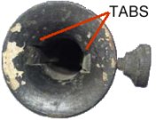 The first Edison sockets in 1879 and until late 1880 were wooden
sockets that did not yet have the Edison screw base for the bulb.
The oldest bulbs had wires sticking out of the end, which were normally
folded under or slipped between two metal tabs. These tabs were
then held by winding thread around the top of the tabs, which held
them tight against the base of the bulb.
The first Edison sockets in 1879 and until late 1880 were wooden
sockets that did not yet have the Edison screw base for the bulb.
The oldest bulbs had wires sticking out of the end, which were normally
folded under or slipped between two metal tabs. These tabs were
then held by winding thread around the top of the tabs, which held
them tight against the base of the bulb. 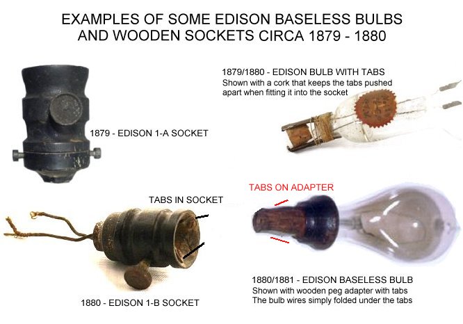
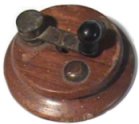 In
1879/1880, the No. 1 sockets were sometimes used with a standard
telegraph switch (as shown on your right) to turn it off and on,
though it included the earliest thumb screw type of switch on the
side of the socket (as shown on your left). Note that these thumb
screw knobs were made of brass as it is hard to tell from the photos.
In
1879/1880, the No. 1 sockets were sometimes used with a standard
telegraph switch (as shown on your right) to turn it off and on,
though it included the earliest thumb screw type of switch on the
side of the socket (as shown on your left). Note that these thumb
screw knobs were made of brass as it is hard to tell from the photos.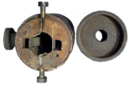 An improvement with the 1-B was made in which the wires no longer
connect to the outside of the socket (as seen on the pictures of
the 1-A above), but now come down through the bottom hole like you
are used to seeing on sockets even today. This was not the case
on the No. 1-A version (shown clearly in the picture on your right),
even though when simply looking at it and seeing the hole on the
bottom and thinking that the wires would come down through it. The
wires were connected on the outside to the terminal screws shown
above on the sides of the socket and the hole on the bottom was
simply to connect it to a fixture with the wires connecting from
the outside of the socket.
An improvement with the 1-B was made in which the wires no longer
connect to the outside of the socket (as seen on the pictures of
the 1-A above), but now come down through the bottom hole like you
are used to seeing on sockets even today. This was not the case
on the No. 1-A version (shown clearly in the picture on your right),
even though when simply looking at it and seeing the hole on the
bottom and thinking that the wires would come down through it. The
wires were connected on the outside to the terminal screws shown
above on the sides of the socket and the hole on the bottom was
simply to connect it to a fixture with the wires connecting from
the outside of the socket.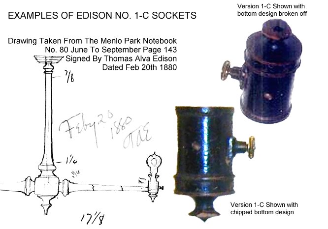
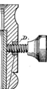
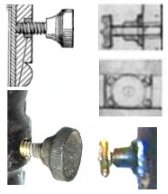 This
No. 1-C sockets have a new design in the thumb screw switch and
now a more ornate knob which is different from the earlier 1-A and
1-B sockets. This is easy to compare from the photo's above (in
the 1-A section) to the sockets shown directly above and the drawing
shown below (example clips on the right).
This
No. 1-C sockets have a new design in the thumb screw switch and
now a more ornate knob which is different from the earlier 1-A and
1-B sockets. This is easy to compare from the photo's above (in
the 1-A section) to the sockets shown directly above and the drawing
shown below (example clips on the right). 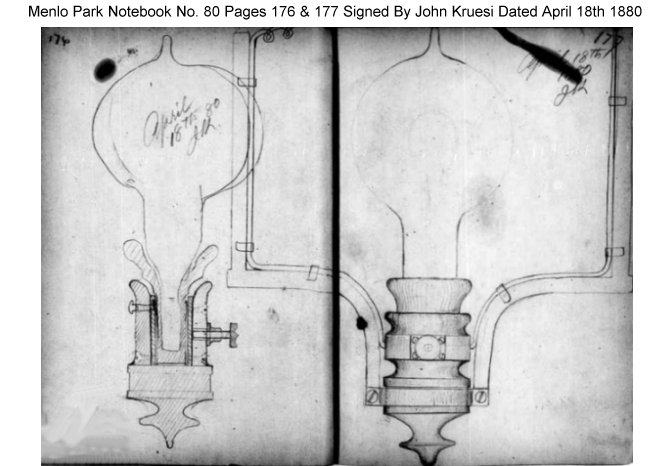
 In
the Jehl book there is a picture of a four socket chandelier
in Vol. one on page 409 shown on your right, in which he says
about it:
In
the Jehl book there is a picture of a four socket chandelier
in Vol. one on page 409 shown on your right, in which he says
about it: